MPU6050加速度计 陀螺仪传感器
MPU6050介紹
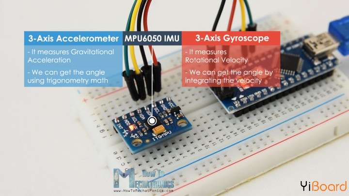
MPU6050是一种微电子机械系统(MEMS),在单芯片上集成了一个3轴加速度计和一个3轴陀螺仪,还有温度传感器,使用I2C 通信接口。
它可以测量:
- 加速度
- 速度
- 方向
- 移位
- 温度
MPU6050 IMU也称为六轴运动跟踪设备或6 DoF(六自由度)设备,因为它有6个输出,即3个加速度计输出和3个陀螺仪输出。
MPU6050加速度计测量加速度的方式与ADXL345加速度传感器相同。简而言之,它可以测量沿3个轴的加速度,结合一些三角学数学,我们可以计算传感器定位的角度。因此,如果我们融合或组合加速度计和陀螺仪数据,我们可以获得有关传感器方向的非常准确的信息。
三轴陀螺仪
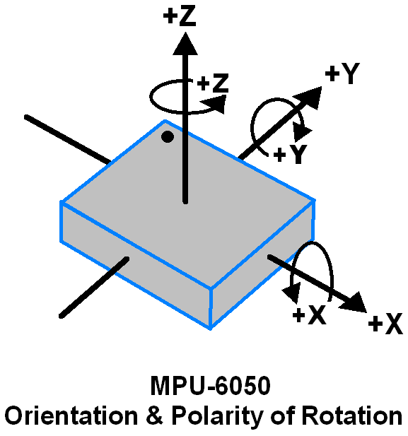
MPU6050 由采用微机电系统 (MEMS) 技术的 3 轴陀螺仪组成。用于检测沿 X、Y、Z 轴的旋转速度,如下图所示。
-
当陀螺仪围绕任何传感轴旋转时,科里奥利效应会引起振动,MPU6050 内部的 MEM 会检测到该振动。
-
产生的信号被放大、解调和过滤以产生与角速率成正比的电压。
-
该电压使用 16 位 ADC 进行数字化以对每个轴进行采样。
-
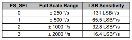
输出的满量程范围为 +/- 250、+/- 500、+/- 1000、+/- 2000。
-
陀螺仪输出各轴角速度,单位为度/每秒。
-
因此为了获得角度值,我们只需要对其进行积分。
三轴加速度计
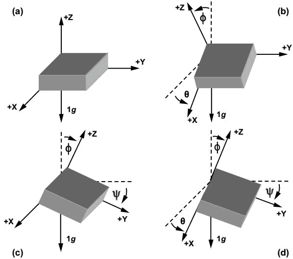
MPU6050 由采用微机电 (MEMS) 技术的 3 轴加速度计组成。它用于检测沿 X、Y 和 Z 轴的倾斜或倾斜角度,如下图所示。
-
沿轴的加速度使可移动质量偏转。
-
移动板(质量)的这种位移使差分电容器不平衡,从而导致传感器输出。输出幅度与加速度成正比。
-
16 位 ADC 用于获得数字化输出。
-
加速度的满量程范围为 +/- 2g、+/- 4g、+/- 8g、+/- 16g。
-
它以 g(重力)为单位测量。
-
当设备放置在平面上时,它将在 X 和 Y 轴上测量 0g,在 Z 轴上测量 +1g。
DMP(数字运动处理器)
嵌入式数字运动处理器 (DMP) 用于计算运动处理算法。它从陀螺仪、加速度计和额外的 3rd 方传感器(如磁力计)获取数据并处理数据。它提供了滚动、俯仰、偏航角、横向和纵向感等运动数据。它最大限度地减少了主机计算运动数据的过程。结果数据可以从 DMP 寄存器中读取。
片上温度传感器
片上温度传感器输出使用 ADC 数字化。温度传感器的读数可以从传感器数据寄存器中读取。
MPU6050模块
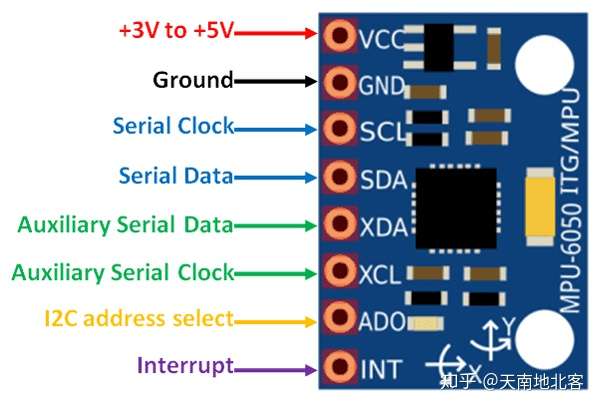
MPU-6050 模块有 8 个引脚,
- INT:中断输出引脚。传感器数据可读时为高。
- AD0: I2C 从地址 LSB 引脚。这是设备的 7 位从地址中的第 0 位。如果连接到 VCC,那么它被读取为逻辑 1,默认为0。因此模块的默认I2C地址为 0x68。如果将AD0接VCC,则I2C地址为 0x69,这样一个MCU可以连接两个MPU6050。
- XCL:辅助串行时钟引脚。此引脚用于将其他启用 I2C 接口的传感器 SCL 引脚连接到 MPU-6050。
- XDA:辅助串行数据引脚。此引脚用于将其他启用 I2C 接口的传感器 SDA 引脚连接到 MPU-6050。
- SCL:串行时钟引脚。将此引脚连接到微控制器 SCL 引脚。
- SDA:串行数据引脚。将此引脚连接到微控制器 SDA 引脚。
- GND:接地引脚。将此引脚连接到接地连接。
- VCC:电源引脚。将此引脚连接到 +3 ~ 5V 直流电源。
该模块两个辅助引脚XDA, XCL,可用于连接外部IIC模块,如3 轴磁力计、压力传感器等进行通信。如果将 3 轴磁力计连接到辅助 I2C 总线,则 MPU6050 可以提供完整的 9 轴 Motion Fusion 输出。
MPU-6050 模块有 Slave 地址(当 AD0 = 0 时,即它不连接到 Vcc)为,
- 从机写地址(SLA+W) : 0xD0
- 从机读地址(SLA+R) : 0xD1
MPU-6050 有各种寄存器来控制和配置其操作模式。因此,请仔细阅读MPU-6050 规格书和MPU-6050 寄存器映射。
Arduino和MPU6050的连接方法
我们来看看如何使用Arduino连接和读取MPU6050传感器的数据。我们使用I2C协议与Arduino进行通信,因此只需要两条线进行连接,另外还有两条线用于供电。
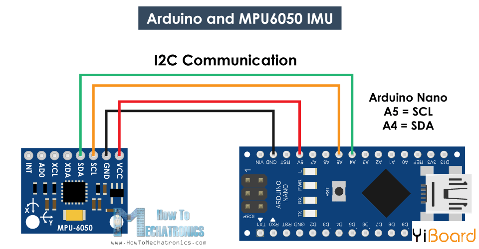
Arduino和MPU6050连接电路图
MPU6050的Arduino代码
以下是用于从MPU6050传感器读取数据的Arduino代码。在代码下方,您可以找到它的详细说明。
/*
   Arduino and MPU6050 Accelerometer and Gyroscope Sensor Tutorial
*/
#include <Wire.h>
const int MPU = 0x68; // MPU6050 I2C address
float AccX, AccY, AccZ;
float GyroX, GyroY, GyroZ;
float accAngleX, accAngleY, gyroAngleX, gyroAngleY, gyroAngleZ;
float roll, pitch, yaw;
float AccErrorX, AccErrorY, GyroErrorX, GyroErrorY, GyroErrorZ;
float elapsedTime, currentTime, previousTime;
int c = 0;
void setup() {
  Serial.begin(19200);
  Wire.begin();                      // Initialize comunication
  Wire.beginTransmission(MPU);       // Start communication with MPU6050 // MPU=0x68
  Wire.write(0x6B);                  // Talk to the register 6B
  Wire.write(0x00);                  // Make reset - place a 0 into the 6B register
  Wire.endTransmission(true);        //end the transmission
  /*
  // Configure Accelerometer Sensitivity - Full Scale Range (default +/- 2g)
  Wire.beginTransmission(MPU);
  Wire.write(0x1C);                  //Talk to the ACCEL_CONFIG register (1C hex)
  Wire.write(0x10);                  //Set the register bits as 00010000 (+/- 8g full scale range)
  Wire.endTransmission(true);
  // Configure Gyro Sensitivity - Full Scale Range (default +/- 250deg/s)
  Wire.beginTransmission(MPU);
  Wire.write(0x1B);                   // Talk to the GYRO_CONFIG register (1B hex)
  Wire.write(0x10);                   // Set the register bits as 00010000 (1000deg/s full scale)
  Wire.endTransmission(true);
  delay(20);
  */
  // Call this function if you need to get the IMU error values for your module
  calculate_IMU_error();
  delay(20);
}
void loop() {
  // === Read acceleromter data === //
  Wire.beginTransmission(MPU);
  Wire.write(0x3B); // Start with register 0x3B (ACCEL_XOUT_H)
  Wire.endTransmission(false);
  Wire.requestFrom(MPU, 6, true); // Read 6 registers total, each axis value is stored in 2 registers
  //For a range of +-2g, we need to divide the raw values by 16384, according to the datasheet
  AccX = (Wire.read() << 8 | Wire.read()) / 16384.0; // X-axis value
  AccY = (Wire.read() << 8 | Wire.read()) / 16384.0; // Y-axis value
  AccZ = (Wire.read() << 8 | Wire.read()) / 16384.0; // Z-axis value
  // Calculating Roll and Pitch from the accelerometer data
  accAngleX = (atan(AccY / sqrt(pow(AccX, 2) + pow(AccZ, 2))) * 180 / PI) - 0.58; // AccErrorX ~(0.58) See the calculate_IMU_error()custom function for more details
  accAngleY = (atan(-1 * AccX / sqrt(pow(AccY, 2) + pow(AccZ, 2))) * 180 / PI) + 1.58; // AccErrorY ~(-1.58)
  // === Read gyroscope data === //
  previousTime = currentTime;        // Previous time is stored before the actual time read
  currentTime = millis();            // Current time actual time read
  elapsedTime = (currentTime - previousTime) / 1000; // Divide by 1000 to get seconds
  Wire.beginTransmission(MPU);
  Wire.write(0x43); // Gyro data first register address 0x43
  Wire.endTransmission(false);
  Wire.requestFrom(MPU, 6, true); // Read 4 registers total, each axis value is stored in 2 registers
  GyroX = (Wire.read() << 8 | Wire.read()) / 131.0; // For a 250deg/s range we have to divide first the raw value by 131.0, according to the datasheet
  GyroY = (Wire.read() << 8 | Wire.read()) / 131.0;
  GyroZ = (Wire.read() << 8 | Wire.read()) / 131.0;
  // Correct the outputs with the calculated error values
  GyroX = GyroX + 0.56; // GyroErrorX ~(-0.56)
  GyroY = GyroY - 2; // GyroErrorY ~(2)
  GyroZ = GyroZ + 0.79; // GyroErrorZ ~ (-0.8)
  // Currently the raw values are in degrees per seconds, deg/s, so we need to multiply by sendonds (s) to get the angle in degrees
  gyroAngleX = gyroAngleX + GyroX * elapsedTime; // deg/s * s = deg
  gyroAngleY = gyroAngleY + GyroY * elapsedTime;
  yaw =  yaw + GyroZ * elapsedTime;
  // Complementary filter - combine acceleromter and gyro angle values
  roll = 0.96 * gyroAngleX + 0.04 * accAngleX;
  pitch = 0.96 * gyroAngleY + 0.04 * accAngleY;

  // Print the values on the serial monitor
  Serial.print(roll);
  Serial.print("/");
  Serial.print(pitch);
  Serial.print("/");
  Serial.println(yaw);
}
void calculate_IMU_error() {
  // We can call this funtion in the setup section to calculate the accelerometer and gyro data error. From here we will get the error values used in the above equations printed on the Serial Monitor.
  // Note that we should place the IMU flat in order to get the proper values, so that we then can the correct values
  // Read accelerometer values 200 times
  while (c < 200) {
    Wire.beginTransmission(MPU);
    Wire.write(0x3B);
    Wire.endTransmission(false);
    Wire.requestFrom(MPU, 6, true);
    AccX = (Wire.read() << 8 | Wire.read()) / 16384.0 ;
    AccY = (Wire.read() << 8 | Wire.read()) / 16384.0 ;
    AccZ = (Wire.read() << 8 | Wire.read()) / 16384.0 ;
    // Sum all readings
    AccErrorX = AccErrorX + ((atan((AccY) / sqrt(pow((AccX), 2) + pow((AccZ), 2))) * 180 / PI));
    AccErrorY = AccErrorY + ((atan(-1 * (AccX) / sqrt(pow((AccY), 2) + pow((AccZ), 2))) * 180 / PI));
    c++;
  }
  //Divide the sum by 200 to get the error value
  AccErrorX = AccErrorX / 200;
  AccErrorY = AccErrorY / 200;
  c = 0;
  // Read gyro values 200 times
  while (c < 200) {
    Wire.beginTransmission(MPU);
    Wire.write(0x43);
    Wire.endTransmission(false);
    Wire.requestFrom(MPU, 6, true);
    GyroX = Wire.read() << 8 | Wire.read();
    GyroY = Wire.read() << 8 | Wire.read();
    GyroZ = Wire.read() << 8 | Wire.read();
    // Sum all readings
    GyroErrorX = GyroErrorX + (GyroX / 131.0);
    GyroErrorY = GyroErrorY + (GyroY / 131.0);
    GyroErrorZ = GyroErrorZ + (GyroZ / 131.0);
    c++;
  }
  //Divide the sum by 200 to get the error value
  GyroErrorX = GyroErrorX / 200;
  GyroErrorY = GyroErrorY / 200;
  GyroErrorZ = GyroErrorZ / 200;
  // Print the error values on the Serial Monitor
  Serial.print("AccErrorX: ");
  Serial.println(AccErrorX);
  Serial.print("AccErrorY: ");
  Serial.println(AccErrorY);
  Serial.print("GyroErrorX: ");
  Serial.println(GyroErrorX);
  Serial.print("GyroErrorY: ");
  Serial.println(GyroErrorY);
  Serial.print("GyroErrorZ: ");
  Serial.println(GyroErrorZ);
}
代码描述:首先我们需要包含用于I2C通信的Wire.h库,并定义一些存储数据所需的变量。
在setup()函数部分,我们需要初始化wire库并通过电源管理寄存器复位传感器。 为此,我们需要查看传感器的数据手册,从中我们可以看到寄存器地址。

MPU6050电源管理寄存器0x6B
此外,如果需要,我们可以使用配置寄存器为加速度计和陀螺仪选择满量程范围。 对于这个例子,我们将使用加速度计的默认±2g范围和陀螺仪的250度/秒范围。
// Configure Accelerometer Sensitivity - Full Scale Range (default +/- 2g)
  Wire.beginTransmission(MPU);
  Wire.write(0x1C);                  //Talk to the ACCEL_CONFIG register (1C hex)
  Wire.write(0x10);                  //Set the register bits as 00010000 (+/- 8g full scale range)
  Wire.endTransmission(true);
  // Configure Gyro Sensitivity - Full Scale Range (default +/- 250deg/s)
  Wire.beginTransmission(MPU);
  Wire.write(0x1B);                   // Talk to the GYRO_CONFIG register (1B hex)
  Wire.write(0x10);                   // Set the register bits as 00010000 (1000deg/s full scale)
  Wire.endTransmission(true);
  */
在loop()函数部分,我们首先读取加速度计的数据。 每个轴的数据存储在两个字节或寄存器中,我们可以从传感器的数据手册中看到这些寄存器的地址。
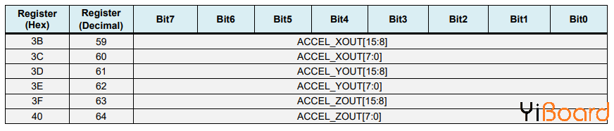
MPU6050 imu加速度计数据寄存器
为了全部读取它们,我们从第一个寄存器开始,然后使用requiestFrom()函数,我们请求读取X、Y和Z轴的所有6个寄存器。 然后我们从每个寄存器读取数据,并且由于输出是二进制补码,我们将它们相应地组合以获得正确的值。
// === Read acceleromter data === //
  Wire.beginTransmission(MPU);
  Wire.write(0x3B); // Start with register 0x3B (ACCEL_XOUT_H)
  Wire.endTransmission(false);
  Wire.requestFrom(MPU, 6, true); // Read 6 registers total, each axis value is stored in 2 registers
  //For a range of +-2g, we need to divide the raw values by 16384, according to the datasheet
  AccX = (Wire.read() << 8 | Wire.read()) / 16384.0; // X-axis value
  AccY = (Wire.read() << 8 | Wire.read()) / 16384.0; // Y-axis value
  AccZ = (Wire.read() << 8 | Wire.read()) / 16384.0; // Z-axis value
为了获得-1g到+ 1g的输出值,适合计算角度,我们将输出除以先前选择的灵敏度。
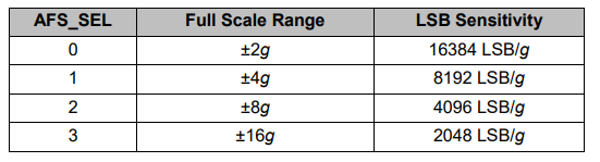
mpu6050加速度计灵敏度满量程范围
最后,使用这两个公式,我们从加速度计数据计算滚转角和俯仰角。
 accAngleX = (atan(AccY / sqrt(pow(AccX, 2) + pow(AccZ, 2))) * 180 / PI) - 0.58; // AccErrorX ~(0.58) See the calculate_IMU_error()custom function for more details
  accAngleY = (atan(-1 * AccX / sqrt(pow(AccY, 2) + pow(AccZ, 2))) * 180 / PI) + 1.58; // AccErrorY ~(-1.58)
接下来,使用相同的方法我们得到陀螺仪数据。
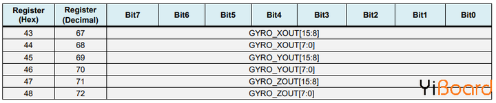
我们读取了六个陀螺仪寄存器,适当地组合它们的数据并将其除以先前选择的灵敏度,以便以每秒的度数获得输出。
// === Read gyroscope data === //
  previousTime = currentTime;        // Previous time is stored before the actual time read
  currentTime = millis();            // Current time actual time read
  elapsedTime = (currentTime - previousTime) / 1000; // Divide by 1000 to get seconds
  Wire.beginTransmission(MPU);
  Wire.write(0x43); // Gyro data first register address 0x43
  Wire.endTransmission(false);
  Wire.requestFrom(MPU, 6, true); // Read 4 registers total, each axis value is stored in 2 registers
  GyroX = (Wire.read() << 8 | Wire.read()) / 131.0; // For a 250deg/s range we have to divide first the raw value by 131.0, according to the datasheet
  GyroY = (Wire.read() << 8 | Wire.read()) / 131.0;
  GyroZ = (Wire.read() << 8 | Wire.read()) / 131.0;
在这里你可以注意到我用一些小的计算误差值来校正输出值,我将在接下来解释它们是如何得到它们的。 因此,当输出以度/秒为单位时,现在我们需要将它们与时间相乘以得到度数。 使用millis()函数在每次读取迭代之前捕获时间值。
// Correct the outputs with the calculated error values
  GyroX = GyroX + 0.56; // GyroErrorX ~(-0.56)
  GyroY = GyroY - 2; // GyroErrorY ~(2)
  GyroZ = GyroZ + 0.79; // GyroErrorZ ~ (-0.8)
  // Currently the raw values are in degrees per seconds, deg/s, so we need to multiply by sendonds (s) to get the angle in degrees
  gyroAngleX = gyroAngleX + GyroX * elapsedTime; // deg/s * s = deg
  gyroAngleY = gyroAngleY + GyroY * elapsedTime;
  yaw =  yaw + GyroZ * elapsedTime;
最后,我们使用互补滤波器融合加速度计和陀螺仪数据。在这里,我们采用96%的陀螺仪数据,因为它非常准确,不会受到外力的影响。陀螺仪的缺点是存在漂移,或者随着时间的推移在输出中引入误差。因此,从长远来看,我们使用来自加速度计的数据,本例为4%,足以消除陀螺仪的漂移误差。
// Complementary filter - combine acceleromter and gyro angle values
  roll = 0.96 * gyroAngleX + 0.04 * accAngleX;
  pitch = 0.96 * gyroAngleY + 0.04 * accAngleY;
但是,由于我们无法从加速度计数据计算偏航,我们无法在其上实现互补滤波器。
在我们看一下结果之前,让我快速解释一下如何获得纠错值。为了计算这些错误,我们可以在传感器处于平坦静止位置时调用calculate_IMU_error()自定义函数。在这里,我们为所有输出做了200个读数,我们将它们相加并将它们除以200。由于我们将传感器保持在平坦静止位置,因此预期输出值应为0。因此,通过此计算,我们可以得到传感器的平均误差。
void calculate_IMU_error() {
  // We can call this funtion in the setup section to calculate the accelerometer and gyro data error. From here we will get the error values used in the above equations printed on the Serial Monitor.
  // Note that we should place the IMU flat in order to get the proper values, so that we then can the correct values
  // Read accelerometer values 200 times
  while (c < 200) {
    Wire.beginTransmission(MPU);
    Wire.write(0x3B);
    Wire.endTransmission(false);
    Wire.requestFrom(MPU, 6, true);
    AccX = (Wire.read() << 8 | Wire.read()) / 16384.0 ;
    AccY = (Wire.read() << 8 | Wire.read()) / 16384.0 ;
    AccZ = (Wire.read() << 8 | Wire.read()) / 16384.0 ;
    // Sum all readings
    AccErrorX = AccErrorX + ((atan((AccY) / sqrt(pow((AccX), 2) + pow((AccZ), 2))) * 180 / PI));
    AccErrorY = AccErrorY + ((atan(-1 * (AccX) / sqrt(pow((AccY), 2) + pow((AccZ), 2))) * 180 / PI));
    c++;
  }
  //Divide the sum by 200 to get the error value
  AccErrorX = AccErrorX / 200;
  AccErrorY = AccErrorY / 200;
  c = 0;
  // Read gyro values 200 times
  while (c < 200) {
    Wire.beginTransmission(MPU);
    Wire.write(0x43);
    Wire.endTransmission(false);
    Wire.requestFrom(MPU, 6, true);
    GyroX = Wire.read() << 8 | Wire.read();
    GyroY = Wire.read() << 8 | Wire.read();
    GyroZ = Wire.read() << 8 | Wire.read();
    // Sum all readings
    GyroErrorX = GyroErrorX + (GyroX / 131.0);
    GyroErrorY = GyroErrorY + (GyroY / 131.0);
    GyroErrorZ = GyroErrorZ + (GyroZ / 131.0);
    c++;
  }
  //Divide the sum by 200 to get the error value
  GyroErrorX = GyroErrorX / 200;
  GyroErrorY = GyroErrorY / 200;
  GyroErrorZ = GyroErrorZ / 200;
  // Print the error values on the Serial Monitor
  Serial.print("AccErrorX: ");
  Serial.println(AccErrorX);
  Serial.print("AccErrorY: ");
  Serial.println(AccErrorY);
  Serial.print("GyroErrorX: ");
  Serial.println(GyroErrorX);
  Serial.print("GyroErrorY: ");
  Serial.println(GyroErrorY);
  Serial.print("GyroErrorZ: ");
  Serial.println(GyroErrorZ);
}
我们只需在串行监视器上打印这些值,一旦我们知道它们,我们就可以在前面所示的代码中实现它们,用于滚动和俯仰计算,以及3个陀螺仪输出。
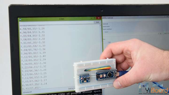
MPU6050俯仰滚转和偏航输出
最后,使用Serial.print函数,我们可以在串行监视器上打印Roll、Pitch和Yaw值,看看传感器是否正常工作。
測試I2C是否連接妥當
使用i2c_scanner sketch測試I2C是否裝置妥當 http://playground.arduino.cc//Main/I2cScanner 執行i2c_scanner sketch,終端機會出現所偵測到的i2c裝置位址。